
Circuit diagram

Components Required:-
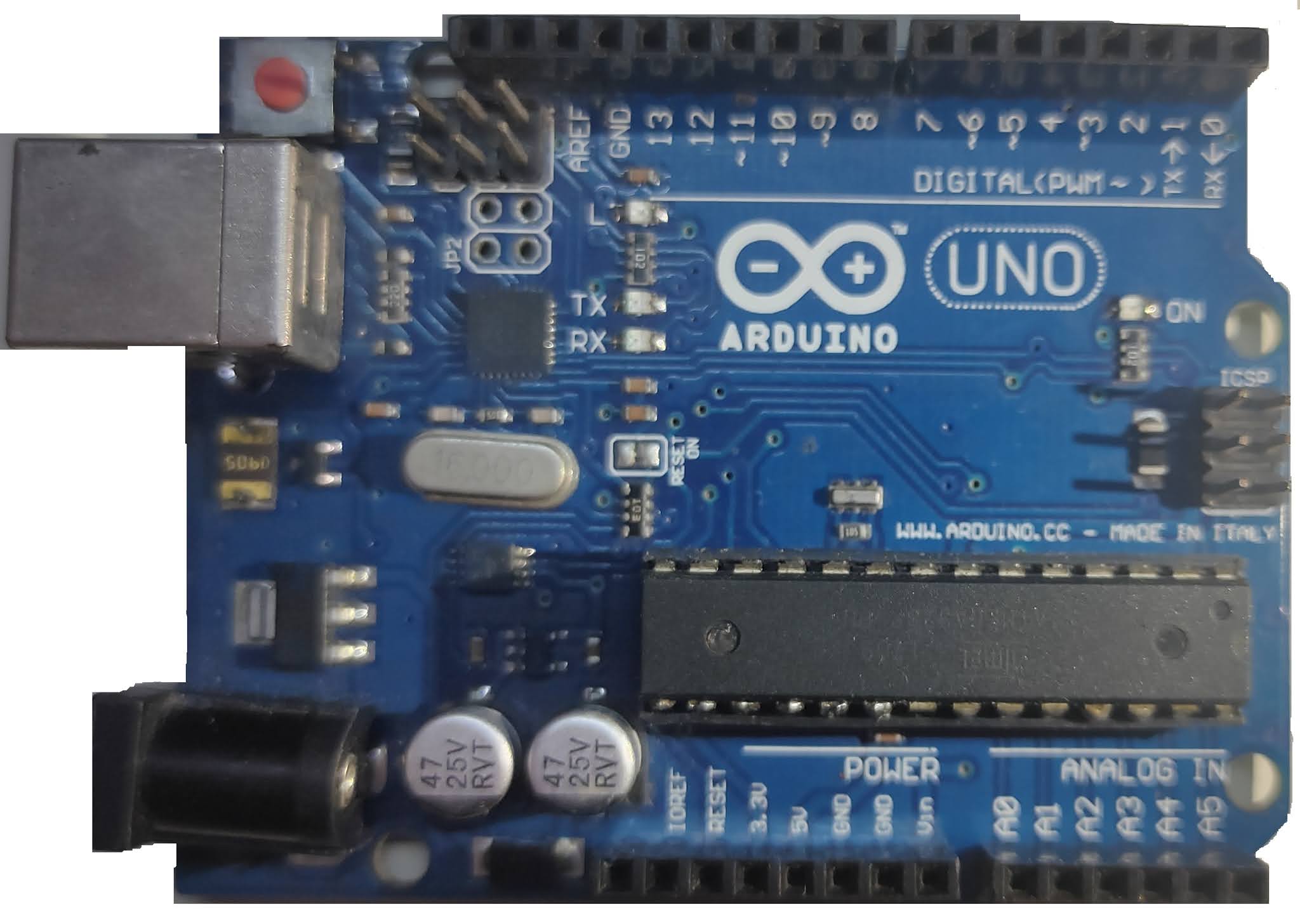
- Arduino Uno :-

- Flame sensor module :-

- 16x2 LCD display :-


- 10K Potentiometer :-


Flame sensor
Flame sensor is a type of detector , whose function is to detect presence of Flame.
If a flame is detected, It provides a digital output signal with logic 1 and if no flame is present, then a digital output of 0 volts is present.

Pinouts:-
1. VCC:- Connect +5Volts over here
2. GND:- Connect GND or 0V over here
3.DO:- Digital Output from module
16x2 LCD display
The name "16x2 LCD display" came from this fact that is has 16 columns and 2 rows , that means we can display 32 characters on this LCD display screen. Characters could be either alphabets, numbers or custom made characters. Each column is made from 5 x 8 matrix of pixels which means 40 pixels per column .


Features:-
- Operating voltage is 4.7V to 5.3V
- Current consumption is 1mA without backlight
- Alphanumeric LCD display module, meaning can display alphabets and numbers
- Can work on both 8-bit and 4-bit mode
- Available in Green and Blue Backlight
Pinouts:-
1. Vss:- Connect GND here
2. Vdd:- Powers the LCD with +5V (4.7V – 5.3V)
3.VEE:-To set contrast of display
4.Register Select:-command/data register
5.Read/Write:-Used to read or write data. Normally grounded to write data to LCD
6.Enable:- To enable Read/Write on LCD
7. Data bit 0:- To microcontroller to send 8 bit data
8. Data bit 1:- To microcontroller to send 8 bit data
9.Data bit 2:- To microcontroller to send 8 bit data
10.Data bit 3:- To microcontroller to send 8 bit data
11.Data bit 4:- To microcontroller to send 4/8 bit data
12.Data bit 5:- To microcontroller to send 4/8 bit data
13.Data bit 6:- To microcontroller to send 4/8 bit data
14.Data bit 7:- To microcontroller to send 4/8 bit data
15.LED+ :- To set backlight
16.LED- :- To set backlight
Interfacing LCD, Flame sensor, Potentiometer with Arduino

- First connect flame sensor with Arduino by connecting VCC pin to 5 V of Arduino, GND pin to GND pin of Arduino, DO pin to A0 pin of Arduino.
- Then Connect LCD screen with Arduino by connecting Vss & LED- pin to GND pin of Arduino.
- Vdd & LED+ pin to 5V of Arduino.
- VEE pin to potentiometer's 2nd pin .
- RS pin to 6th pin of Arduino.
- R/W pin to 7th pin of Arduino.
- E pin to 8th pin of Arduino.
- DB4 pin to 9th pin of Arduino.
- DB5 pin to 10th pin of Arduino.
- DB6 pin to 11th pin of Arduino.
- DB7 pin to 12th pin of Arduino.
- Then Connect 1st terminal of potentiometer to 5V and 3rd terminal to GND of Arduino.
Arduino Code
____________________________________________________________
#include <LiquidCrystal.h>
LiquidCrystal lcd(6,7,8,9,10,11,12);
int flame,sensor=A0,detected=0,buzzer=A1;
void setup()
{
pinMode(sensor,INPUT);
pinMode(buzzer,OUTPUT);
lcd.begin(16,2);
}
void loop()
{
flame=digitalRead(sensor);
lcd.clear();
if(flame==detected)
{
lcd.print("Fire detected");
lcd.setCursor(0,1);
lcd.print("alarms are on");
digitalWrite(buzzer,HIGH);
}
else
{
lcd.print("All set");
lcd.setCursor(0,1);
lcd.print("alarms are off");
digitalWrite(buzzer,LOW);
}
delay(100);
}
____________________________________________
To understand this project in detail then please watch my tutorial on YouTube by CLICKING HERE or on this image:-

Comments
Post a Comment